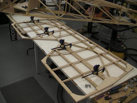
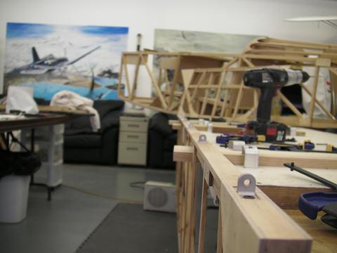
ATTACHING TAIL PIECES
Attaching HS
.jpg)

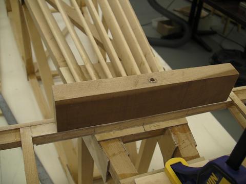
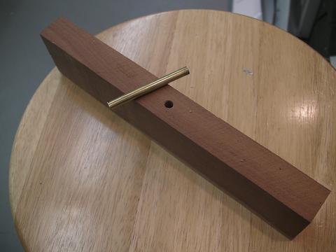
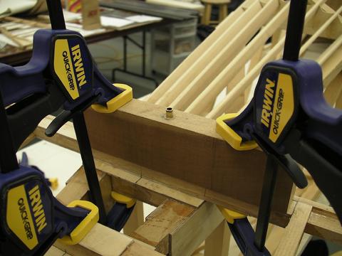
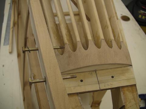
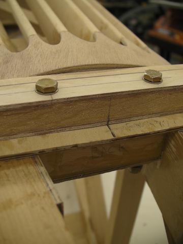
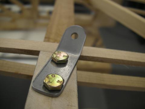
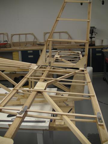
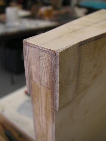
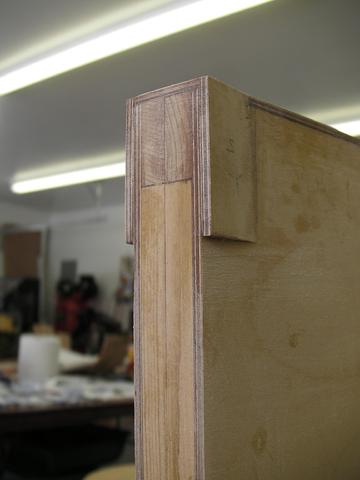
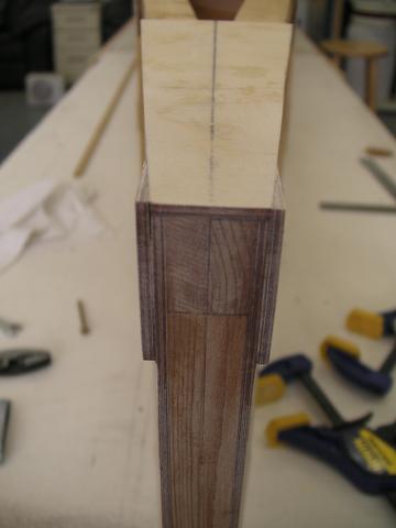
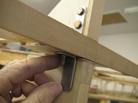
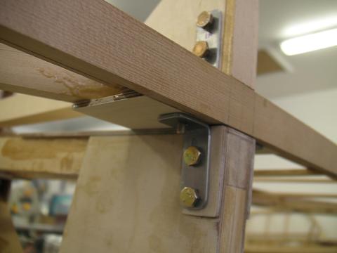
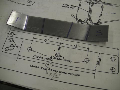
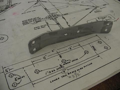
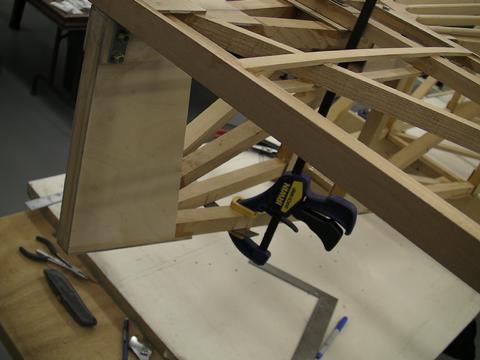
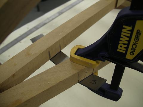
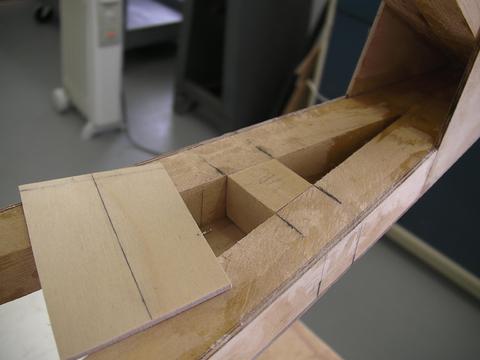
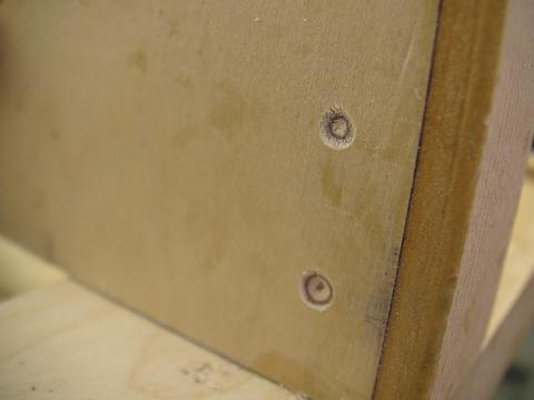
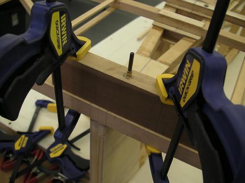
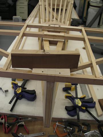
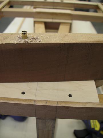
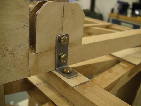
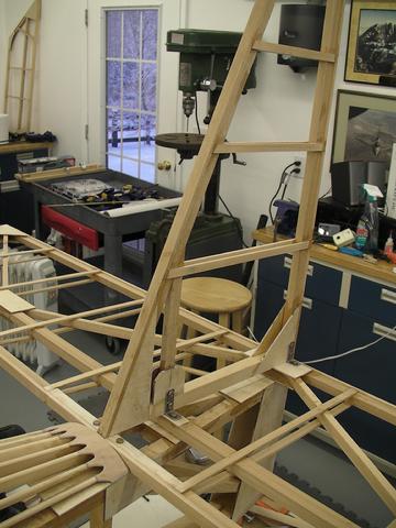
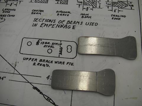
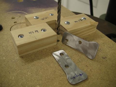
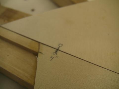
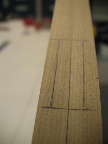
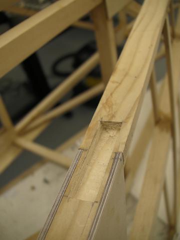
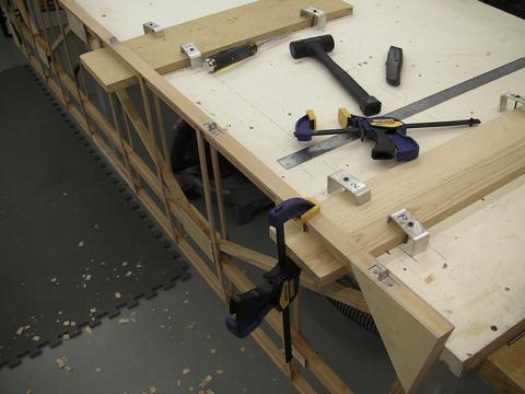
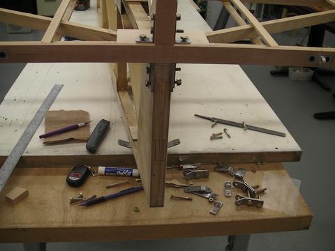
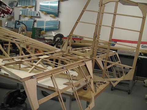
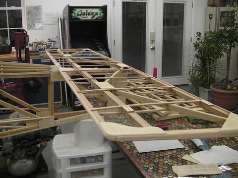
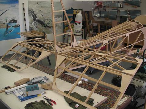
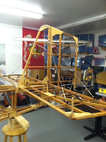
Attaching the Horizontal Stabilizer...3 Feb 2010 Tonight I marked the Horizontal Stab forward bolts for drilling. I'm using AN3-28 bolts here so I planned on using a 3/16" drill bit. In order to ensure a straight drill hole (over 2" long), I fashioned a drill bit jig. Using a piece of hard wood, I dilled a whole all the way thru, using my drill press, for a clean vertical hole. I then inserted a piece of brass tubing (the only tubing of the right size I could find at the hardware store) which had an inside diameter of 3/16" the same size as the drill bit. I then started the two holes by eye to make an indent, and clamped the wood to the top of the HS. Then, using a long, 3/16" drill bit and a cordless drill, I carefully drilled the holes. The bolts were able to be inserted fairly tight, but incredibly accurate and straight. The nuts on the bottom will be accessible thru an inspection hole I plan to put on the rear of the fuselage. Overall, the drill jig and hole drilling went fairly fast and came out great. **I can't over emphasize the anxiety of drilling your first holes in major components of the aircraft. Ready to press on!Hours: 1.06 Feb 2010 Cut and epoxied HS gussets to fit the braces. I used 1/4" finish birch and sanded them thinner to contour with the other HS pieces.Hours: 1.07-10 Feb 2010 I drilled the HS brace holes using my drill jig. All holes drilled straight and true, except for one. It must have angled slightly. I decided to fill the hole with epoxy and the next day I redrilled the hole and came out much better. I finished up the HS braces by making the appropriate bend angle. I installed all the HS braces temporarily (temp bolts). I then made wedges for the lower HS stab hold down pieces. I made these from spruce plywood, sanded down to form the correct angles. I made these as small as possible to minimize the influence on wind flow. I then drilled the two holes and installed the HS lower hold down pieces. Then I fashioned the lower tail brace and marked the area. I installed a piece of 1' spruce and 1/8" plywood top and bottom for the bolts.Hours: 4.0
Attaching the VS

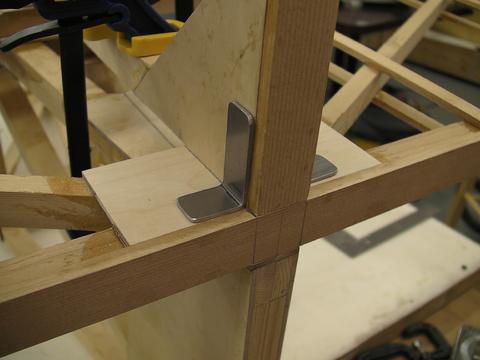
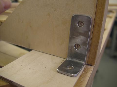
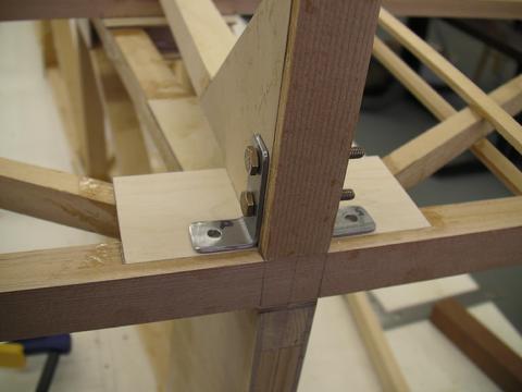
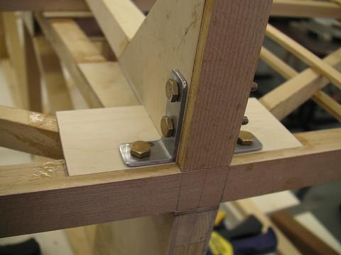
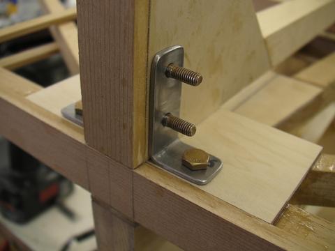
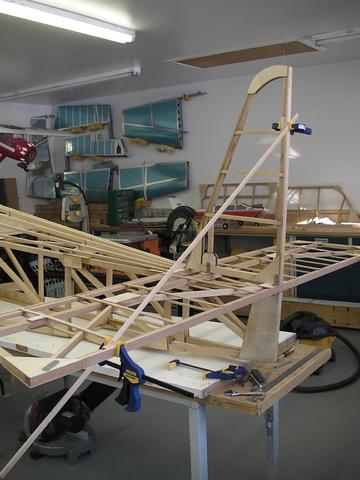
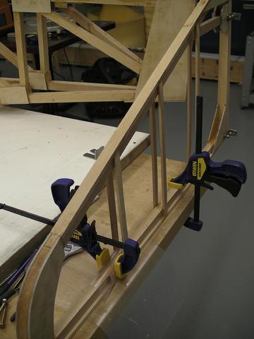
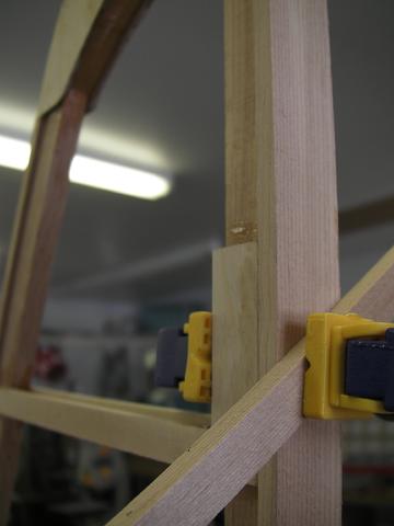
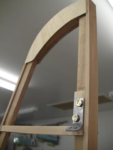
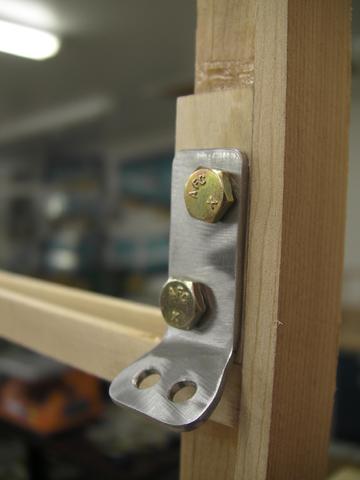
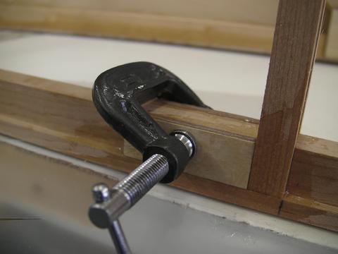
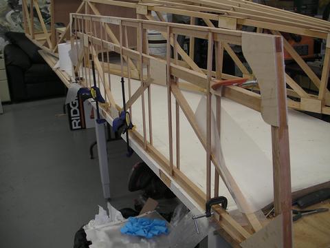
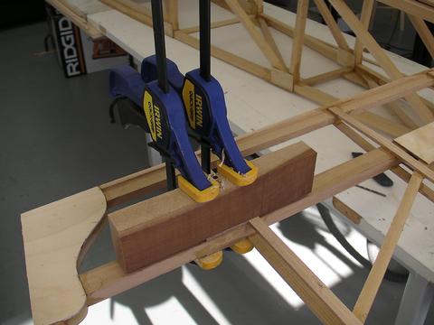
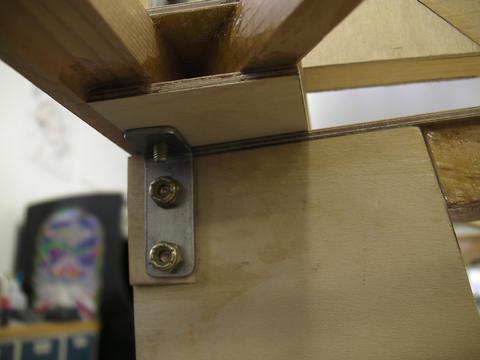
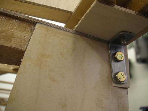
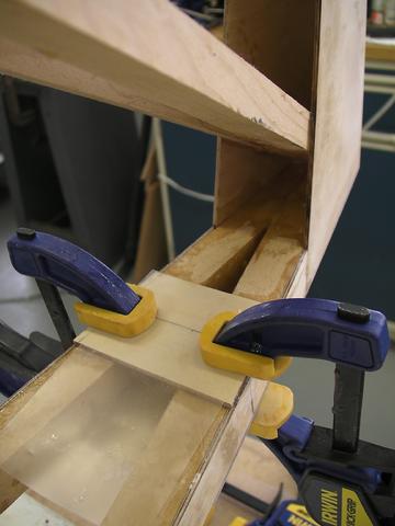
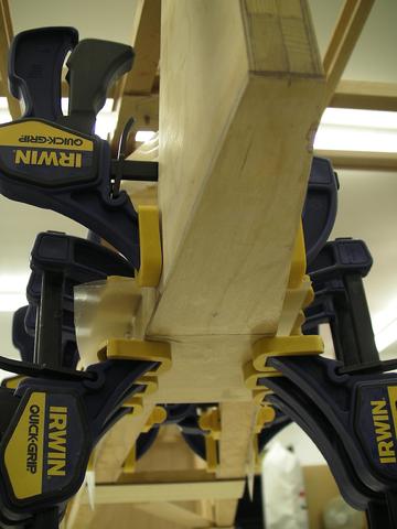
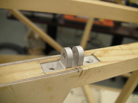
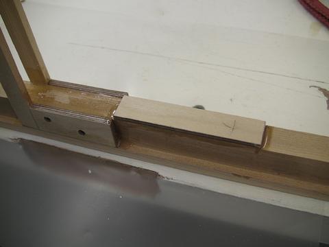
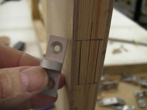
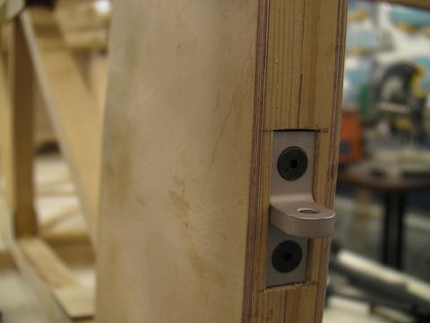
3 Feb 2010 Today was very productive. I drilled holes in the VS hold-down metal parts and installed the VS. I am using temporary AN3 bolts, which are over sized length, to help in removing. The drill jig worked great and all bolts fit perfectly snug.Hours: 2.06-7 Feb 2010 Cut and epoxied the VS upper gussets to fit the braces. I used 1/4" finish birch and sanded them thinner to contour with the other VS pieces. The braces were made using .09, 4130 and I modified the one end to accept two separate wire braces.Hours: 1.0
Attaching Rudder and Elevators

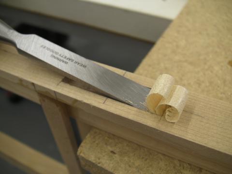
15- 20 Feb 2010 Worked on attaching the elevators. I purchased hinges at Brodhead and decided to use a hand chisel to make the recessed spaces for them on the elevator, rudder and stabilizers.Hours: 4.0
Finishing Tail Feather Edges
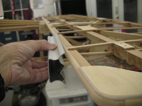
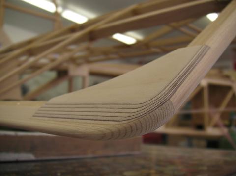
15- 20 Nov 2010 Sanded the edges of all tail feather surfaces, by hand using a flat sanding block and a rounded sanding tool. I used mostly 60-80 grit paper, and made all corners as symmetrical as possible with it's opposite corner.Hours: 6.0
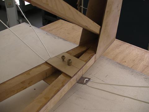
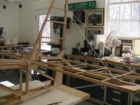
Tail Bracing Wires
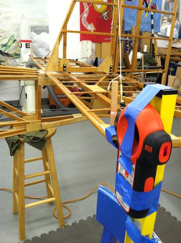
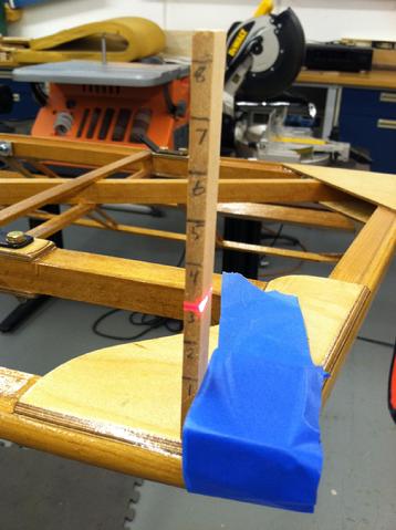
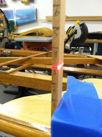
15 Jan - 1 Feb 2012: Made bracing wires for the tail feathers out of 3/32 SS cables, shakles, and turnbuckles. I had preliminarily leveled all tail surfaces as best as possible. After completing all the cables and attaching, it was time to adjust the leveling to close tolerences. I used a lazer and homemade leveling devices. Shot from a short distance away, the lazer is leveled on two different points on the HS at a time. It took about 30 mins to make each cable (working slow), and about two hours of adjusting to get the cable tension just right.Hours: 6.0